Step 1: Sketching the product’s mechanical solution.
This stage involves the theoretical analysis of the problem and the definition of mechanical solutions needed to address it through an innovative product. At this point, validations are still very early and theoretical, so it doesn’t make much sense to create the final part drawing booklet just yet.
Step 2: Drawings for the MVP (Minimum Viable Product)
An innovative product usually involves more than one hypothesis or area of uncertainty. According to our proprietary method, each critical element must be tested in a basic way through Minimum Viable Products (MVPs) that allow us to practically demonstrate whether the proposed solution makes sense.
The part drawings for an MVP don’t hold significant value either, mainly because the purpose of drawings is to transfer definitive knowledge, geometries, and part specifications. Since an MVP is a rudimentary version meant to validate hypotheses, the part and component drawing booklet still lacks relevance at this stage.
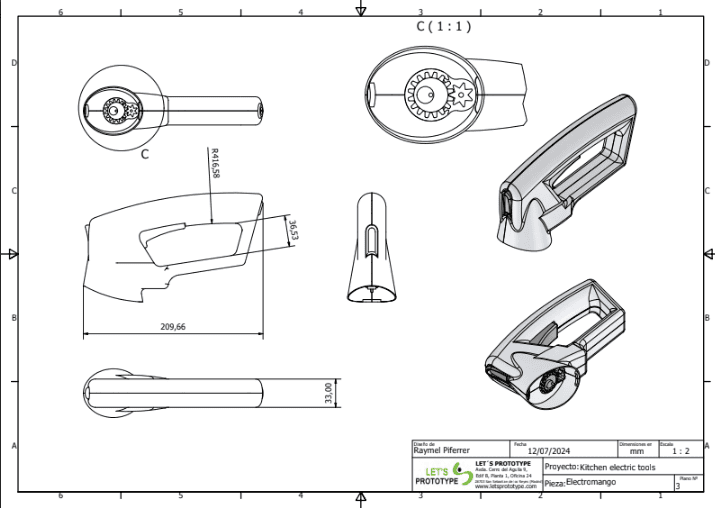
Step 3: Drawings for the first prototype version
The knowledge gained from the hypothesis validation cycle enables the optimization of the design and the subsequent manufacturing of a functional prototype. This design process uses industrial design software that allows for the following:
Simulate scenarios and study behaviors: Scenario simulation makes it possible to validate the behavior, strength, and functionality of the designed parts projected in the drawings, all in a digital environment. Before manufacturing, we can determine the most suitable materials for each part and even estimate the product life cycles of each component.
Generate manufacturing files: After completing the necessary theoretical validations and design optimizations, industrial design software enables the generation of manufacturing files. These manufacturing files serve as an ideal language to communicate or transfer the part designs to the machines that will produce the components of the prototype. The part drawings are also a valuable tool in this process, as they act as reference documents for verifying the quality of the final parts.
The part and component drawings act as a language for transferring knowledge and information about the design of a product’s essential parts or prototype. For this reason, there are established norms and drawing structure standards. Adhering to these standards ensures that the information presented in the drawings can be efficiently understood by professionals across the industry.
On the other hand, missing information or failure to follow these standards can hinder the effective transfer of knowledge expected from product part drawings.
Part name and technical identification: Each part drawing must include the name of the part. It’s recommended to use intuitive names that reflect the part’s function or purpose within the product. Likewise, the drawing title should include a unique identifier—such as a code—that links to additional information in the technical documentation, such as usage, assembly method, material details, and more.
Material specification: Design drawings must always include the specific type of material required for manufacturing. In the case of prototypes, given the limitations of available manufacturing methods, it’s common to indicate the material to be used for the validation version, as well as the recommended material for the final industrial product.
Drawing scale: For obvious reasons, part drawings often cannot be displayed at actual size. Therefore, the scale of the projected drawing must always be indicated. This refers to the size ratio between the real dimensions of the part and the size represented in the drawing booklet.
Part designer and date: For traceability purposes, it is essential to identify the designer responsible for the part, as well as the date of design drawing creation. This information ensures proper version control and traceability of updated part designs.
Revision: It is good practice to identify the design version of the part represented in the drawing. This field helps prevent errors in version control and traceability, as outlined in the previous point.
Assembly identification: Another important field in part design drawings is the identification of the assembly to which the part belongs. At Let’s Prototype, this field is always completed with the project name, which is agreed upon with the client before starting any design work.
Technical views in design drawings: Part drawings should include multiple views of the part—typically front, side, and top views. Including these design views in the drawing booklet improves understanding of the part and facilitates quality analysis during the manufacturing process.
Sections and cut views: When dealing with designed parts that are part of a complex mechanical system, or when the parts serve as housings for other components, it is considered best practice to include sectional or cut views in the drawings. These views allow for clear visualization of the internal features of the designed parts.
Dimensions: A key piece of information in part design drawings is the set of dimensions. The design drawings must document linear measurements—length, width, and height—as well as hole diameters, radii, and part thicknesses. Another critical aspect of the dimensions section is the specification of dimensional tolerances, which should be documented both generally and specifically for features that are critical to the part’s function. When parts include threads, chamfers, or holes designed to fit other components, it is essential to detail the depths of these features.
Technical finish specifications: The section for technical specifications in design drawings includes information related to the finishing details of the part. In most cases, these finishes are essential to the proper function of the design. For example, this includes required tolerances and surface treatments such as galvanizing, painting, or anodizing.
Use of standard symbols: This refers to a legend of drawing icons fully defined by ISO quality standards or ASME guidelines. These symbols allow for easy identification of welds, surface finishes, or internal threads present in the part.
The design drawings of a part have always been valuable files for part reproduction as well as for quality inspection after the manufacturing process. For this reason, regardless of the industrial manufacturing method used for each component, it is essential that the technical documentation of a product includes an up-to-date and properly documented drawing booklet.
However, it is also true that most of the machines used in manufacturing processes are now equipped with digital systems capable of reading and operating based on three-dimensional data. This reality—greatly enhancing the reliability of part production—makes it highly recommended to transfer part design information using other file formats generated by standard product design software, such as the STEP format.
If you're interested in learning more about the deliverables provided after the design and prototyping processes we develop at Let’s Prototype, we’ll be happy to answer any questions. On the other hand, if you'd like to see some examples of part drawings properly documented, just reach out to us — we’ll gladly share sample prototype drawings developed in our invention lab.